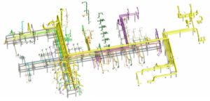
CAE Piping offers a complete package of the piping design and engineering for both metallic and plastic piping systems:
-
-
- Producing the piping drawings, isos.
- Design of the piping systems and mechanical components.
- Performing the pipe stress analysis and selecting the required type of the pipe supports ( Anvil, B-line,.., Custom design pipe supports).
- Producing the calculation’s drawings, to report the loads acting on the pipe supports.
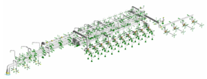
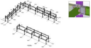
- Design of the pipe support, pipe racks, and pipe skids to support the piping systems, conduits, and cable trays.
- Design of the foundation for the pipe racks and pipe supports.
-

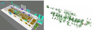
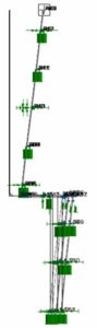
Pipe Stress Analysis
CAE Piping performs Pipe Stress Analysis based on ASME codes (American Boiler and Pressure vessel). ASME codes cover the design, analysis, manufacturing and inspection of pressure vessels, piping and supporting structures. It represents a complete set of rules for the analysis of the mechanical components too.
We perform pipe stress analyses for the various loading conditions such as:
- Normal Operating Conditions
- Upset Conditions
- Emergency Conditions
- Faulted Conditions
We follow ASME B31 standard in the piping design and engineering for the power and process plants and industrial and commercial facilities under various loading conditions such as the weight, thermal, seismic, wind and other dynamic loads. We follow ASME B31 and section III codes and NRC regulations in the piping design of the power plants.
We perform static analyses for the following loading conditions:
Pressure:
Operating pressure or upset condition pressures.
Deadweight:
This loading condition consists of the weight of pipe, medium, insulation and any attachment to the pipelines.
Wind Loads:
This loading condition is a dynamic condition but normally analyzed as an equivalent static condition.
Thermal Loads:
This loading condition is induced by different thermal transients.
Thermal Stratification:
This loading condition occurs in the connecting pipes in a horizontal plane between two reservoirs with fluid at different temperatures with small flow rates. This initiates an extra bending stress and creates local stresses in the pipe cross section due to a nonlinear circumferential metal temperature distribution. Pressurizers’ surge lines are one of the places where thermal stratification occurs.
Equipment Movements:
This loading condition causes the movement of pipes due to thermal movement of the equipment or pressure vessels and the movement of the pipe supports due to seismic loads.
Dynamic analyses are performed for the following occasional loading conditions:
Water Hammer/Steam Hammer Loads (Transient slug analysis) :
This loading condition occurs as a result of events that trigger hydraulic transients (like as operational changes). These events may be due to valve opening/closure, pump start-up or a pump trip.
Such events result in pressure waves which travel through the piping systems in a complicated manner including reflected waves, etc.
Vessel Vibrations:
Induced by pipe breaks in pressure vessels, pumps, and valves.
Seismic (Earthquake) and Other Building Induced Loads:
This is constituted by the dynamic pipe support movements, during a seismic event, and the response to these movements depends on the dynamic characteristics of the considered piping systems and their attachments in relation to the characteristics of the loading.
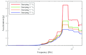
We perform Finite Element Analysis for the following occasional loading conditions (earthquake, water hammer, etc.).
- Transient dynamic analysis yields the response of the piping system, if the dynamic excitations are known in terms of time histories of support movements.
- Response spectrum analysisis used in the assessment of structural integrity, if the loads are given in terms of the floor response spectrum. If not, we can even provide the floor response spectrum too, based on the ground motion at the site location.
- Equivalent static analysis can be used when just the ground movements are available, based on ASCE 7-10.
Pipe Supports Design
We design the primary Pipe Support based on ASME, ASCE, IBC, CBC and AISC codes (American Institute of Steel Construction). We perform the stress analyses based on ASME section VIII for the supporting structures of the piping systems that are designed by following ASME B31 codes (power and process pipelines). We follow ASME section III for the analysis of pipe supports of power piping systems.
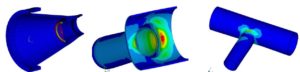
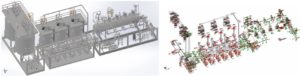
Our CAE engineers create 3D models of the pipe supports and perform the finite element analysis on the 3D solid/shell model. So, one can see an analyzed 3D models of the pipe supports in the stress report.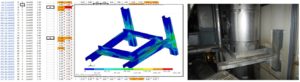
Design of Pipe Racks and Pipe Skids
We design the secondary Pipe Supports, pipe racks and pipe skids, based on ASME, ASCE, IBC, CBC and AISC codes.
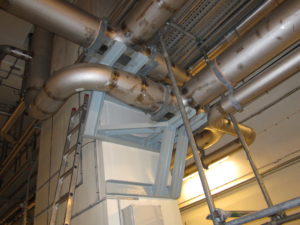
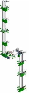
Design of Pipe Risers
CAE Piping offers the design of the Vertical Pipe Risers based on ASME, ASCE and AISC codes. We design vertical pipe riser isolation springs, required pipe guides and anchors and custom vibration isolation.
Analysis of Piping Equipment
CAE Piping performs engineering analyses on the piping equipment such as valves, flanges, gaskets, nozzles, weld lugs, embedded welding plates and wall penetrations, etc. The analyses are performed based on ASME Section VIII, Division II, and WRC Bulletins 107, 297 and 368 and other applicable codes.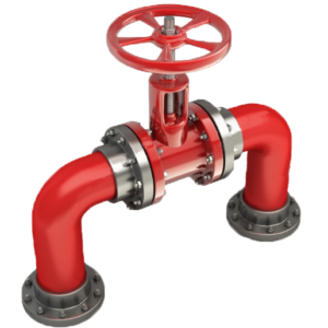
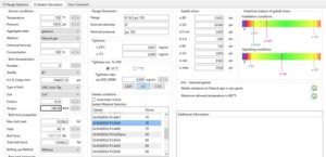
We perform detailed flange analysis to check the stress in the flanges, estimate the min/max torques required for the bolts and to define the type of the required gaskets.
Beside data provided in ASME codes and WRC’s Bulletins, CAEP performs advanced 3D non-linear finite element analysis to estimate the SIFs (Stress Intensification Factors) for different piping components such as tees, elbows, etc.